Ok, I decided to change my computer a couple of months right now. But as Intel is doing some strange stuffs with the prices, this took a little longer than exepected. Some friends asked me what I bought, so I decided to write this post.
My new box description:
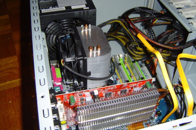
Here a little photo:
So let’s take a look closer.. I bought the Q6600 because it has a good price right now.
For the motherboard I wanted to buy a serious brand (I had some bad issues with ASRock ..). And Asus build some good ones, but doesn’t have a PS2 keyboard plug. I choose the Gigabytes because the bridge cooler is on the right, so I can use a big fan in the case back (no cpu-fan) without the bridge fan issue.
For the harddrive, I already have this type of Seagate on another box (in ATA, not SATA), and it’s damn cool ! Low noise and great performances .. a substain 58Mo/sec (a little bit more than my previous LVDS-SCSI config at 10 000 rpm !)
The perfect box should have two 120mn fans. So this CoolMaster is fine.
I only use the front fan right now, but this may change in future. The case is quite big (too much for my needs), easy to mount, and serious quality. The hard-drive combo stuff, isn’t really easy to use but it does it’s job.
For the power-supply, after reading a lot of website, I bought the Seasonic. This stuff cost a little money, but it’s a really silent one, and seems to be robust.
As I bought a silent power supply, I needed a silent cpu cooler two. Everybody knows that default Intel fan are awfully noisy, so I decided to test this Freezer. And that was a good choice. On idle, the fan runs at 450 rpm, (hey that’s low!!) and CPU is at 31°. At full load, the fan runs at 1000 rpm (still really low!!) and the CPU is at 46°. My initial plan was to remove the fan on the cooler and to place a big 120 mn on the case back, but haven’t done this yet.
For the video card, I was looking for something with good bench on Linux, so ATI was a good challenger (beside it only works with the latest ATI binary shit). And finding a passive HD2600 is a bit hard.
For the DVD, I didn’t have any ideas. Most DVD players I used are noisy, have unstable speed. My previous Samsung was a real bullshit. I went to me local computer store, and bought the cheaper they have on stock. And this is a really good surprise. This DVD burner is really cool. So, if someone ask, give it a try :)
So, as you can imagine, this little stuff is quite silent and powerfull :)
I will upload some pictures soon …
Update: I took some photos
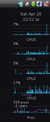
Enjoy cores
