For my next project (another VFD clock ;), I need a small variable PSU. The main issue with the VFD display, is the power supply. In fact you need 2 differents PSU:
- a 5v / 100mA for the filament
- a variable 20 to 75v for anodes..
VFD tube like the IV18 need something like 20/30 volts in direct drive and 50/70 volts where they are muxed. As I can not use them in a direct drive, I need a psu that support output from 20 to 75v, by this way, I can dim the display easily and test the whole stuff in a direct.
I already have done several nixie PSU, but this time I want to build something small (doesn’t cost a lot) with really common parts. I decided to look at smaller mosfet, and I found the BS107 .. small TO92 package and 200v ;)
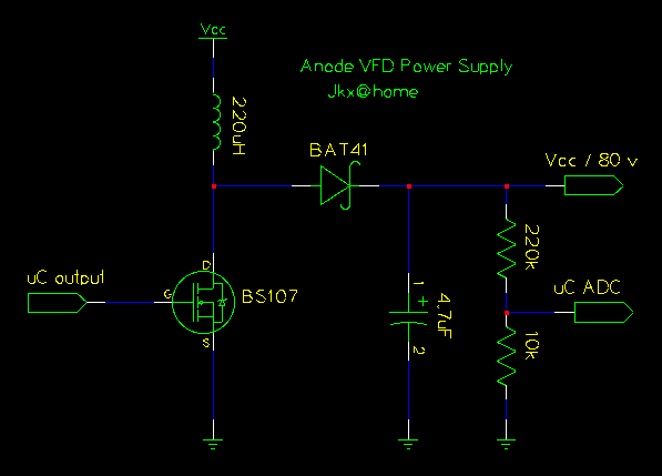
Here the schematic:

With this simple stuff, and a little microcontroler, you can step the output easily. You can use a 220uH inductor with a 5v VCC, or a smaller one 100uH if you have a PSU between 6v to 15v.
/Enjoy the next step

The BS170 is another candidate, because the BS107 has a high Ron (~25 Ohm), and the BS170 not. But the BS170 max output is 60v..
Hi,
just found your note about that simple VFD PSU. I tried it. It generates about 80V without load, with an 2,2kOhm it’s only 20V. What I don’t know how to regulate the output voltage. I tried using PWM but it have nearly no effect besides that the FET gets warm when high phase is long.
Any hints or maybe your regulation software would be nice.
Greetings from Germany
Thorsten
The ouput value depend on the frequency used for the PWM. 220uF, is for the max freq … F_CPU/256 = ~ 30kHz.
If your MOS is getting hot, choose one with a smaller Ron…
Bye
how i know anode of VFD is about +12V…you can simple drive directly from microcontroler (i tryed and it’s work)!
if you put too high voltage on the anode/grid you can damage VFD…
btw: VFD is LOW VOLTAGE TUBE