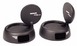
In my home, I have a bad TV antenna, so we use only the cable receiver to watch TV. But I have two TV sets. I decided to buy a video sender a couple of months ago, but never managed to get it working nicely. I bought a Thomson VS360U video sender. This one is really cheap, 24 €, works on the 2.4Ghz for the audio/video and 433Mhz for remote.

At the first test, I discovered that the transceiver come with a couple of IR leds. I have to glue each IR led in front of each part of your equipment I want to drive. For me, the cable receiver, the DVD, the Dvico, and the AV amp .. I tried this, but that’s a mess, each led is soldered on a single string, and tend to move. Not really a nice experience. This is simple to crappy to be use.
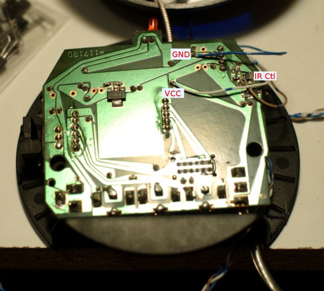
I decided to mod it to be able to use a single IR led, with a better gain. The first step is to find the right place to place my mod. Just open the transceiver, locate the power supply (Vcc/Gnd) and the IR transistor. I was quite easy, the only trick is to solder the wire for the IR transistor just before the base resistor. Here is the result.

You can find a better pix, in the gallery. I used a scope to find the IR transistor, but this can be done without.
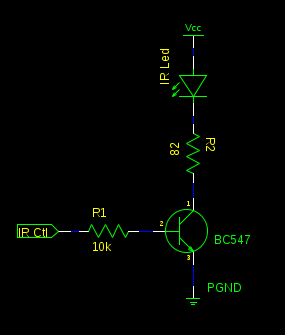
Let’s build a simple IR booster, that’s connect to this pins, and everything will be fine. I used an common BC547 but any common transistor will do the job.

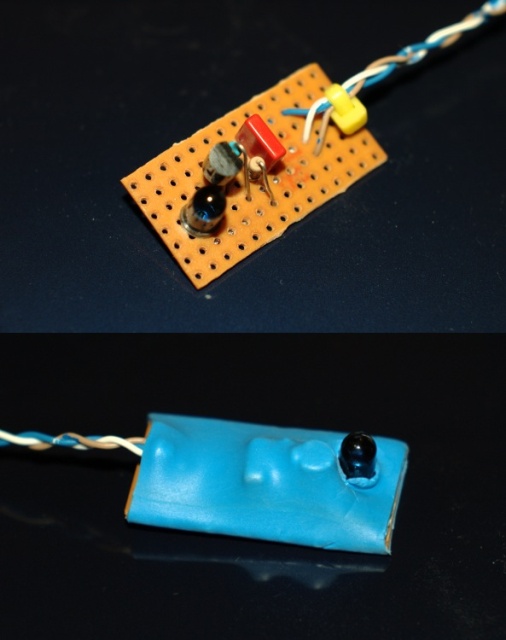
The result :

As you can see, this is small. I placed this near my cable receiver and every is working nicely. I can now control every equipment (cable, DVD, Dvico) for my room without any lag, or IR lost signal.
I managed to fix this cheap video sender without to much effort, I’m happy. This kind of hack can be used in a couple video sender device. The hardest part is to find the IR transistor, the rest is simply the same.
Enjoy TV from bed ;)

I’ve had the same problem and I’m going to implement your design above!
One question though, in the photo of the IR booster circuit, I can see the IR LED, the transistor, 2x resistors and another component (the orange block) that doesn’t appear on your schematic. What is it and is it needed?
Yes, I missed this one. There is a 100nF capacitor between Vcc and GND. The RF part generate a little noise, and I decided to fix that before testing. Anyways, I’m not sure this is really needed. You can try without it.
Hope this help ! Bye . Feel free to ask here, for additionnal question