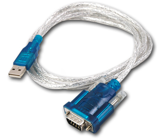
One of the most common way to interface a microcontroler to a computer used to be serial port. But right now, serial port have been replaced with USB on most computers. A common way to fix this issue is to use a USB to TTL converter or a USB to RS232 converter + MAX232. That’s fine but :
- USB to TTL PCB cost a bit of money : you can find some on Ebay around 7€ (shipped) and 15$ on Sparfun !!! That’s about 2 or 5 times the cost of the microcontoler !
- USB to RS232 cost 1.70$ (shipped) but need some extra level shifting and doesn’t really feet on a PCB (need a DB9 connector …)
In fact, USB to RS232 is a mass product, and the cost is really low. I decided to order a couple of this, just to look if I can use this stuff on a PCB. So I bought a 1.70$ USB to RS232 on Ebay.

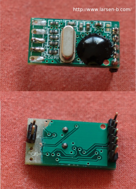
I decided to rip the plastic off the DB9 and discovered a really tiny PCB. I removed the DB9, and decided to pass this little PCB to a scope session. How the hell do they manage to do a USB to RS232 with only a couple of external components ? They is no big capacitor for level shifter (remember RS232 is a +12/-12v ) ? The answer is simple, they don’t !!
This device isn’t RS232 compliant at all, the signals on the DB9 are TTL compliant, but not RS232. The ouput is between 0/5V and the input can handle -12/+12V but works great with a 0/5V too. I simply removed used pads on one side and added a couple on pins.

Please note that RX pin is missing on this pix but needed of course. The next step : How can I use this with an AVR Atmega (I used a Atmega8 but any will do the trick). Serial connection on a micro is TTL like this board, but the TTL signal is just inverted. A “1″ on the RS232 side is a -12V and +5V on a TTL, and a 0 on the RS232 side is a + 12V and a 0v on the TTL. You can find all the information here.
In fact MAX232 do both level shitting and inverting, but as I’m to lazy to wire a MAX232 (and will destroy the cheap aspect of this hack), I decided to handle this by software. This mean, I won’t be able to use the Atmega serial builtin port but need to write some additional code, to do the RS232 encoding/decoding by hand. Let’s give it a try :

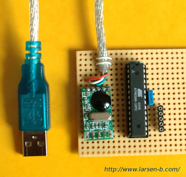
I simply put this on a verroboard, connect VCC to USB Vcc, GND, RX and TX to random pins on the AVR and let’s go to RS232 software serial. This can be done easily in fact, and I managed to handle 19200bauds with the internal 8Mhz clock of the Atmega. Above you will find the popular uart_putc() and uart_getc() ..
 1 #define UART_TX	D,1
 2 #define UART_RX	D,2
 3 #define UART_DELAY	52 // 1/9600 = 104uS : 1/19200 = 52uS
 4
 5
 6 void uart_putc(char c)
 7 {
 8   uchar i;
 9   uchar temp;
10
11   // start
12   set_output(UART_TX);
13   _delay_us(UART_DELAY);
14   clr_output(UART_TX);
15
16   for(i=0;i<8;i++)
17   {
18     temp = c&1;
19     if (temp==0)
20       set_output(UART_TX);
21     else
22       clr_output(UART_TX);
23     _delay_us(UART_DELAY);
24
25      c = c >>1;
26   }
27
28   // stop
29   set_output(UART_TX);
30   _delay_us(UART_DELAY);
31   clr_output(UART_TX);
32
33   _delay_us(UART_DELAY);
34 }
35
36 uchar uart_getc()
37 {
38   uchar i;
39   uchar ib = 0;
40   uchar currentChar=0;
41
42   while (ib != 1)
43     ib = get_input(UART_RX);
44
45   _delay_us(UART_DELAY/2); // middle of the start bit
46   for(i=0;i<8;i++)
47     {
48       _delay_us(UART_DELAY);
49       ib = get_input(UART_RX);
50
51       if (ib ==0)
52 	currentChar |= 1<<i; // this is a 1
53     }
54   return currentChar;
55 }
Nothing more to say, this hack works really great, and I can now build a bunch of USB board without paying so much. The only drawback of this approach is that you can’t use an interrupt for the uart_getc() so you have deal with that in your code. Another approach would use a single transistor for the RX pin to make the RX compliant w/ the AVR serial builtin routine.
You can find the whole project C files + Makefile in a zip here. I think this little hack is really useful, so please send it to all to your DIYer friends, this can save them money, time …
// Enjoy cheap USB ? :)

So is this essentially a $2 FTDI cable? Also, was inverting the bits the reason you couldn’t use the USART module?
Have you thought about inverting your data before writing it to the register for serial data (the same after receiving data). I am not 100% sure but that might do the trick. No need for extra code or cpu cycles.
Greetings
Ferdinand
The chip is not a FTDI but you can use quite the same way.
yes, due to inverting bits, you can’t use the USART module. In fact, for sending this is not a issue, for uart_getc(), you are unable to use the interrupt. But that can be fixed w/ one transistor in between.
Bye
@ferdinand this won’t work cause start/stop bit should be inverted too. so .. for sending this doesn’t each cpu cycle cause sending over USART module eat cpu too .. for receiving, interrupt will be better (depending on your code of course)
Bye
Hello from Russia.
Did you try to add one n-p-n transistor and two resistors for inverting signal?
And Programmer’s Day to you!
I have fought this inversion battle many times.
a simple transistor+resistor will invert the signals easily enough.
It does unfortunately add 4 components to the circuit.
So how is it handled on the PC side? What drivers are needed? How does your PC application access it? What vendor on Ebay did you get your USB-RS232 cable from?
@Alex and @Gar, I haven’t found the time right now. But yes I NPN on the receive pin will provide a nice stuff. (inversion on the send isn’t a big deal) .
@Madge: I used Linux, so no driver is need, works out of the box. Just read/write to /dev/ttyUSB0.
For the ebay vendor, , don’t remember but every cheap (<2$) should work.
Bye
What about using specialized inverter ICs?
(examples: 5-pin 74LVC1G14GW single inverter,
6-pin SN74LVC2G06DCKR double inverter)
If you are not worried about soldering SMD, its:
+ simple (1 only component is possible, no special software)
+ cheap (depending on how you buy, it might still be < 2USD, including the cable)
+ fast (short transition time + hardware UART)
Do you have any idea what the two (or more?) extra pins are for? …any modem control lines?
Have a nice day!
how did you pull the rs232-side housing apart? I destroyed one of these a few months back trying to cut the plastic off
@bernt, I missed this comment (don’t know how). Yes simple inverter will do the trick. I don’t have some here so, never tried this.
The other lines are standard db9 lines, so yes modem control ones.
@Bob, I cut the plastic w/ a knife, and cut the db9 pins before.
bernt,
I was using a 7404 on mine and it worked well. There definitely aren’t any handshaking lines hooked up on these converters
I’ve been playing with this for the last day, and I’m not having success. I found an identical looking cable, but the board inside is slightly different. Still, I identified the pins. I hooked RX and TX together, and using cutecom I am receiving exactly what I am sending each time, so I know the cable itself is working properly.
Using your code on the AVR, I’m sending “a\r\n”, and that’s it. However, using cutecom I only see things like x00 repeated over and over. Is there something else that I need to do on the software side in order to translate the messages, or am I just missing something huge?
This is the first time I’ve delved into serial comm before, so please be gentle.
@Phillip : don’t forget to swap RX and TX from the AVR to RS232 converter:
AVR === RS232
RX < === TX
TX ===> RX
Newer PIC mcu:s have settings to invert the hardware USART, that is good because it can be used directly with the cheap USB-serial converters.
is this cable compatibile with atmega328p?
salut
Nemanja
Yes, just change the code if needed